
Heat 2 Power:
New Thermo Storage Technology [ ]
]
- The decoupling of heat should be secondary at this point, but still possible. The priority with the New Thermal Storage Technology is the generation and smoothing of electricity. Heat to Power !
-
Previous heat accumulators clearly differentiate between charging and discharging cycles. The New Thermal Storage Technology should function as a system in which this is possible simultaneously through separate media circuits. What is the benefit?
- Several heat sources supply their energy to the storage tank at irregular intervals. However, the the subsequent heat engine should run continuously.
- Charging and discharging curcuits can use different fluids. External heat transfer or decoupling of heat to a secondary circuit is therefore not required.
- The heat input occasionally falls below the minimum temperature required by a subsequent heat engine. However, it can still generate electricity continuously. Overall, constant operation for subsequent power generation without frequent starting and stopping of the heat engine is assured.
- It should also be possible to extract heat for heating purposes in parallel with generating electricity. This makes sense only at certain times of the year if the heat is continuously and consistently available. The required temperature level for this heat is significantly lower than that required for power generation. The New Thermal Storage Technology can easily be configured in a manner that two gas streams of different temperatures are drawn off simultaneously.
- If a subsequent heat engine is installed in the air circuit with a New Thermal Storage, the returning gas flow first returns its residual heat to the storage tank by using a counterflow configuration. In this way, a temperature gradient in the New Thermal Storage is maintained and the temperature level of the hottest modules remains spared.
The New Thermal Storage Technology is ahead of other thermal storage systems with a combination of advantages based on the following points:
- Optimum combination of the materials used in the heat storage mass. A high proportion of steel ensures short response times.
- Charging and discharging takes place in different pipeline systems. So it is not necessary to stop charging to extract heat.
- The storage consists of a package of individual modules that can be controlled independently of one another and in which different temperature levels can also prevail independently of one another.
- The individual modules can be connected in series, in series or in parallel, thus meeting any requirement (charging speed and efficiency, low temperature use, etc.).
- Connecting the modules in series leads to gradual charging or discharging, so that residual heat at a low temperature level can also be used.
- In this way, a countercurrent heat exchange can be implemented, which also enables the use of heat at temperatures that are actually too low for heat engines. Heat at a lower temperature must not be used for heating purposes only, but can participate in the generation of electricity: "Power To Heat To Power".
- Despite its high performance, the system is based on an impressively simple design.
System architecture of the New thermal storage technology
-
One or more thermally insulated enclosures house a heat storage mass made of a fine bulk material, such as quartz sand. The heat storage mass is divided into spatially separated units ("modules"). The modules are connected by pipes.

Example arrangement of the modules
-
Each module of the thermal storage system is traversed by at least two piping systems: the charging piping system (or systems) and the discharging piping system (or systems). The heat transfer media, usually air, flow through these systems in separate circuits. The thermal storage mass is heated or cooled by the flow of the fluid. The fine-grained bulk material and the steel pipes conduct heat approximately like a compact solid.

Symbolic representation of a simple charging
and discharging pipe system of a module.
The piping systems interpenetrate each other; they occupy the same space.
- Outside the thermally insulated housing, there are collecting pipes to distribute the incoming flow to the modules or to collect the outgoing flows from the modules.
- The modules are also interconnected by bypass and return lines, which allow the heat transfer fluid to flow through another module after exiting. This applies to both the charging and discharging pipe systems.
Configuration of the New thermal storage system
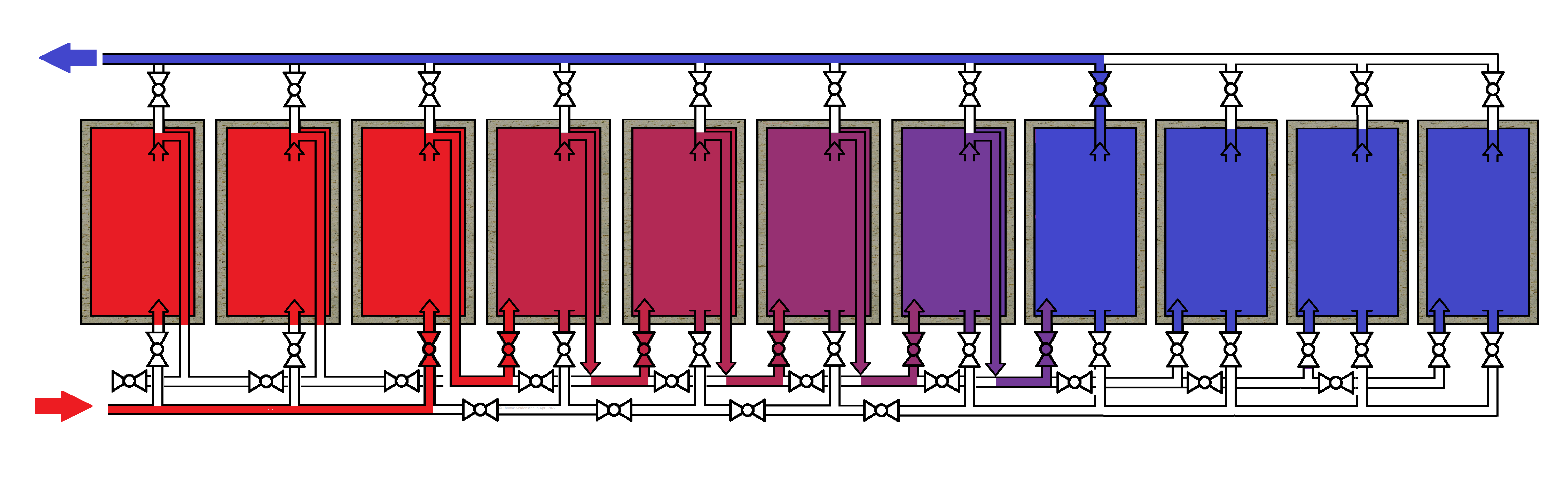
Example configuration: Serial charging of the modules of the HT thermal storage tank
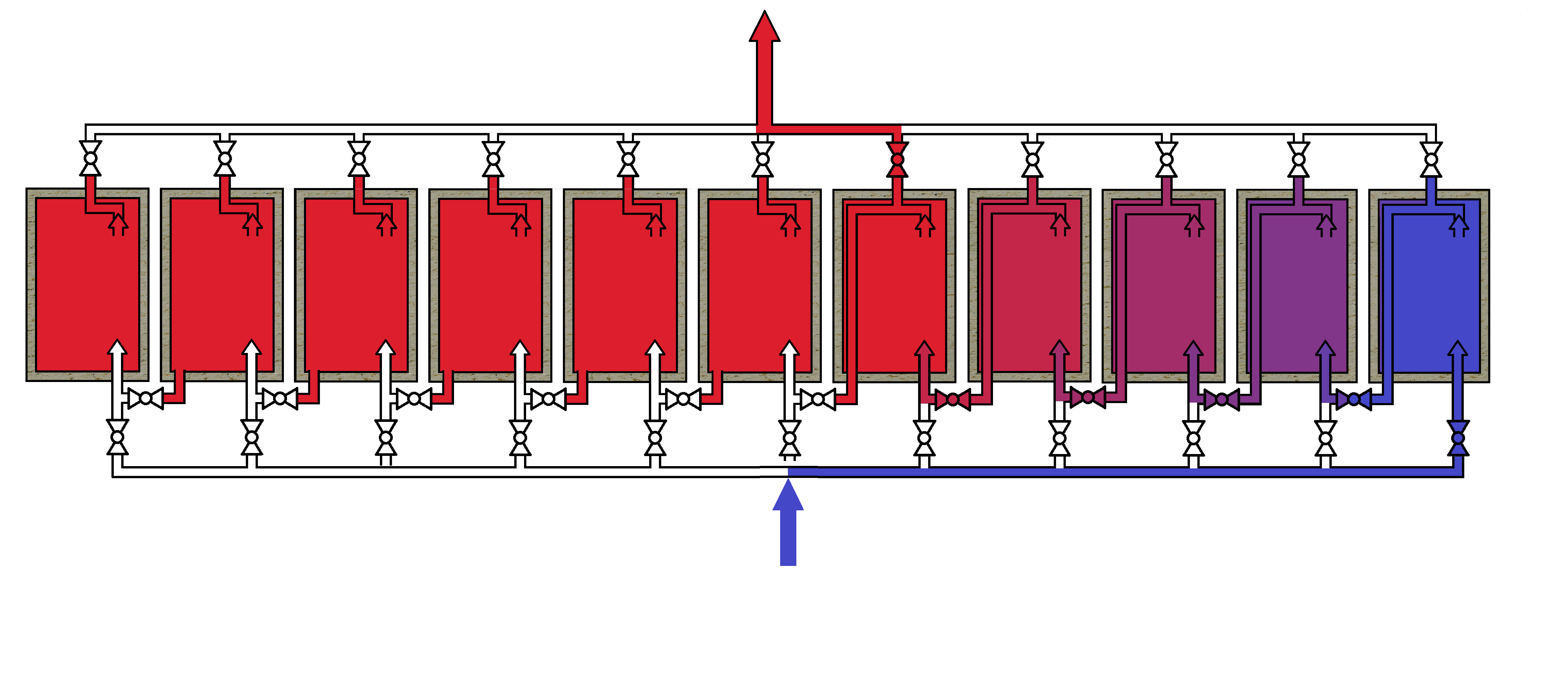
Example configuration: Serial discharge of the modules of the HT thermal storage tank
The heat storage mass
The heat is stored simultaneously in different materials:- Steel piping: The charging and discharging piping systems have a large internal diameter and thick walls. This results in a high proportion of steel by weight in the total heat storage mass.
- Bulk material: Quartz sand is a suitable example. Typical properties: grain size from 0.06 mm, no formation of void bridges, melting point approx. 1500°C.
Structure of the modules
The modules of a storage system are grouped together and located wall-to-wall. Multiple storage systems operate in parallel and can be selectively activated.
Show more technical details
The planned spatial integration of all three piping systems is determined by the installation sequence, the total piping lengths and the thermal flow paths through the storage medium.
The module dimensions are derived from system constraints: air mass flow of the hot gas engine, tube diameter and velocity, permissible pressure drop, heat conduction between the tubes and sand, and standard tube lengths. These parameters define the number of parallel tubes and the overall geometry.
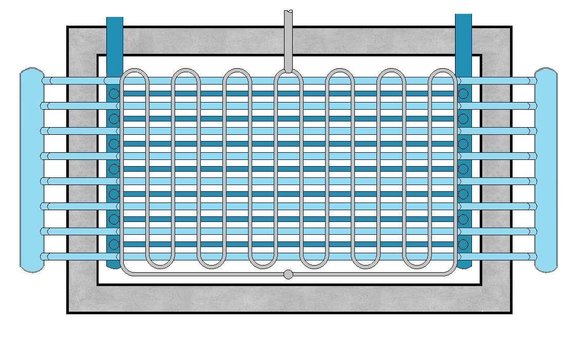
Side view of a heat storage module with three independent piping systems
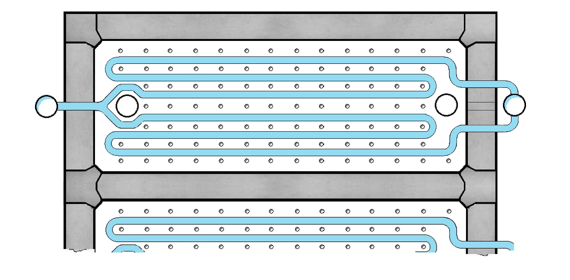
Top view of a heat storage module
How the new thermal storage technology works
Charging: An initial flow of medium circulates between the heat source and the initially cold storage. It is fed to one or more modules via the external distribution piping system. The charging piping system heats the sand bed in which it is embedded through direct contact. The sand itself, the discharging piping system heat up.
After the heat is transferred to the storage unit, the cooled medium returns to the heat source via the external collection line, heats up again there, and then returns to the storage modules.
Discharge: The discharge process occurs independently and, if necessary, simultaneously with the charging process. A second medium flow circulates between the hot heat storage unit and the Heat Engine. Here, the heat extracted from the storage unit is converted into electricity.
During the discharge process, the discharge piping system transfers heat to the heat transfer fluid, which it previously absorbed from the sand. Completely different piping is used for this than for charging.
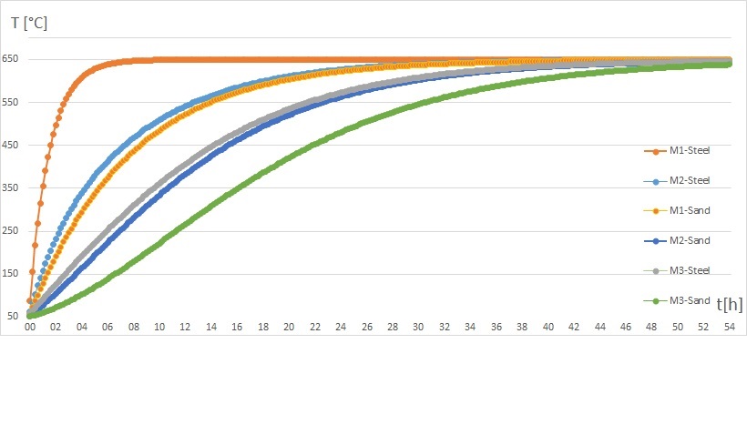
Temperature distribution: The heat is stored in the charging piping system, in the sand and in the discharging piping system and is transferred from one material to the other by direct contact.
The mutual interpenetration of the piping systems ensures a homogeneous distribution of heat within the module. There is no "heat front" propagating inside.
Show more technical details
Most mineral bulk materials are poor conductors of heat. However, the special arrangement of the internal components ensures that every point inside the module is located near a metallic element, and that the heat only has to travel very short distances everywhere.The pipes are designed so that during loading, the innermost section is heated first. During unloading, heat is first absorbed from the outer sections of the heat storage mass, and only then does the hot, inner section flow through. This reduces heat loss to the outer wall.
Charging Dynamics: The modules are connected in series and can be charged and discharged very dynamically. Hot air flows into the first module and heats the internal pipes. The pipes then heat the sand. Since the sand conducts heat more slowly than the metallic components, it heats up with a delay. As the storage mass heats up, the temperature of the exiting air also increases. This heat is used to heat the subsequent modules.
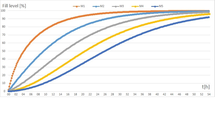
The temperature of the storage mass asymptotically approaches that of the supplied air. As soon as a module is sufficiently charged, the hot air is directly introduced into the next (already preheated) module.
Heat exchange is most efficient at the beginning of the charging process. As the storage mass heats up, the temperature of the outgoing air increases (other heat storage manufacturers omit this fact). Therefore, this heat is used to preheat the subsequent modules.
Control: Temperature measuring devices are linked to a central control unit that actuates valves and thus controls the flow paths.
Depending on the situation and requirements, the modules are therefore subjected to flow during charging and discharging, either individually (alternating), sequentially (serially), simultaneously (in parallel), or in a combination thereof.
Due to heat transfer as the gas flows through a module, it leaves the module with a temperature change compared to the point of entry. When modules are connected in series, a cascade-like temperature change can be achieved across all participating modules. Mixed temperatures can also be achieved by connecting modules in parallel.
This results in numerous possible operating modes of the New Thermal Storage Technology
Contact + Request for licenses
- Dipl. Ing. Thomas Seidenschnur
- info@heat2power.com