Operating Modes of the New Thermo Storage Technology

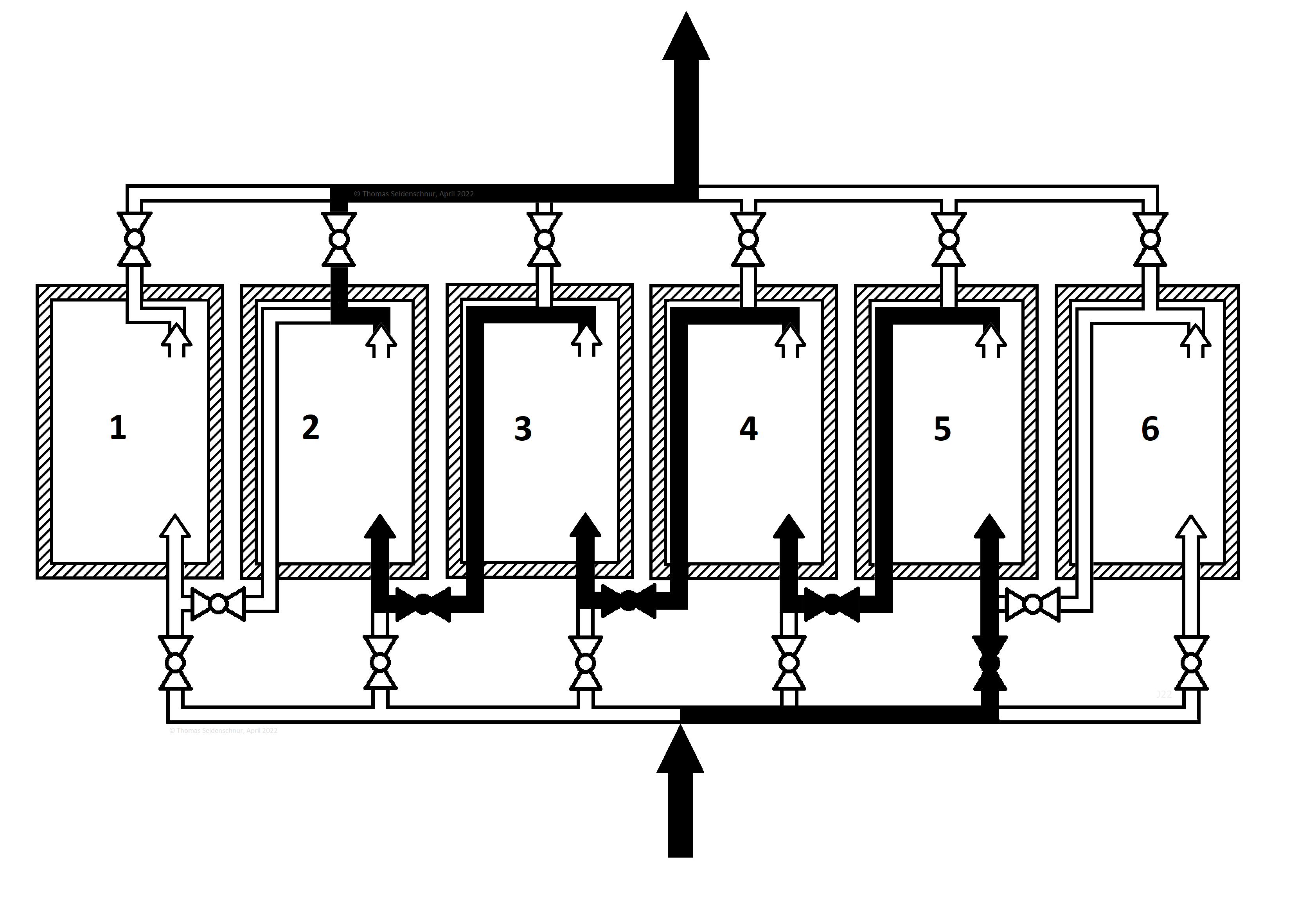
The key point of the New thermal storage technology is, in addition to the simultaneous charging and discharging, the flexible interconnection of the modules each other, which makes it possible
  1. Efficiently distributing and storing of strongly fluctuating energy flows, and
  2. using stored thermal energy at a low temperature level for reconversion, because
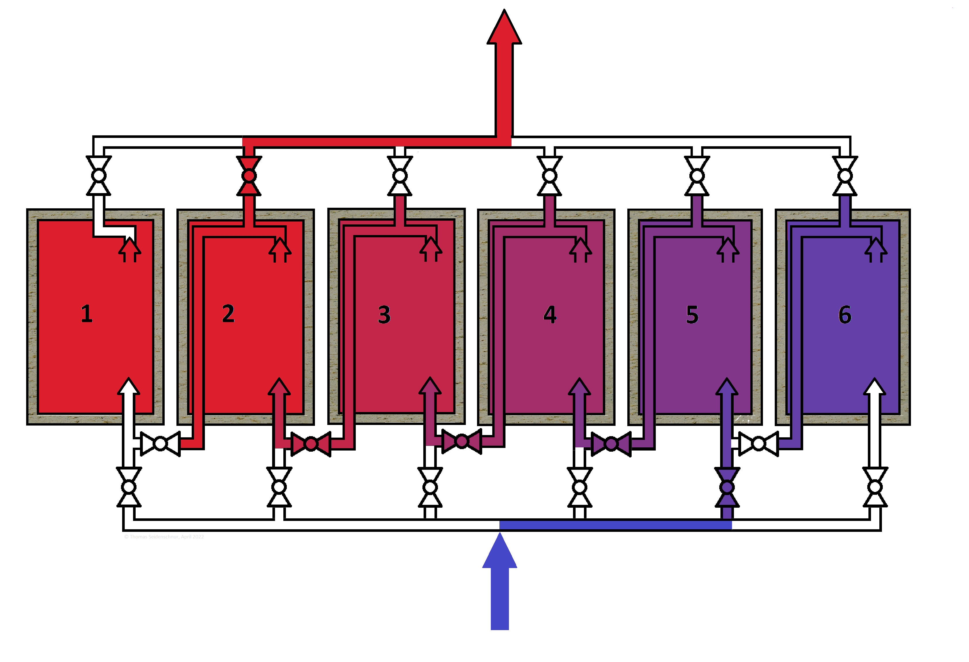
  3. Modules can have different, individual temperatures that
  4. If necessary, flow through them one after the other and thus
  5. Lead a gradual change in temperature of the gas stream.
For this purpose, individual modules are controlled selectively and in a targeted manner and connected in series or parallel or a combination of these as required.

The activation or deactivation and the order in which the heating medium flows through the individual modules is controlled electronically and automatically with valves. Temperature gauges on each module are linked to a central electronic controller which operates valves to control the flow paths to and between the modules

Why is this necessary? Subsequent heat engine for reconversion require a minimum temperature. The higher the temperature, the higher the efficiency. It is useless if all modules of the heat storage have a temperature of 450°C, for example. It is better if at least one hot module quickly reaches 600°C and another initially only 300°C.

Successive charging of individual modules


The amount of supplied heat is concentrated here through the external distribution or charging pipe and given to module 5, and the temperature only rises there. Modules 1 to 4 are already charged. When the desired temperature of the storage mass is reached, a switch is made to another module.
The medium then leaves the system through an external manifold and returns to the heat source.
With this mode of operation, heat can be applied in a targeted and concentrated manner to a specific module. This mode is also advantageous if a smaller amount of heat that is available for a longer period of time is fed in, but it should be ensured that at least one module should always have a minimum temperature.

In this way, a selected module also can be specifically reheated.

Parallel Charging


Parallel charging of individual modules
The amounts of heat supplied and the rise in temperature are the same for the involved modules 1-6 ; the maximum temperature is only reached somewhere in the system at the end of the entire charging process.
This operating mode is advantageous if a very large amount of heat (e.g. peak power from wind energy) is to be distributed evenly.

Parallel and partially serial charging of individual modules


The inflowing hot heat transfer medium initially gives off energy simultaneously to -for example- the first three modules. Its temperature approximates that of the incoming gas over time and the heat exchange efficiency deteriorates. It then leaves these areas via internal return flow lines with a relatively high residual temperature and then flows into the subsequent module 4 via an external bypass line. The heat transfer medium cools down further here.

This process is repeated in the downstream modules 5 and 6, so that the medium is gradually cooled and the modules 4-6 are gradually heated, each with a lower temperature. The gas flow then leaves module 6 with minimum temperature and only then flows back to the heat source through the external outlet line
Since the efficiency of the heat exchange is greatest at high temperature differences, it decreases continuously in the two first-mentioned operating modes in the modules involved, and a lot of heat circulates in the charging flow. However, serial charging leads to the fact that the residual heat (after heating the first three modules) is also used, provided the last modules flowed through are still correspondingly cold.

Serial Charging


The consistent application of serial charging: The medium flow reaches module 1 via the external inlet pipe. It then flows to the next module via the internal return flow pipe and external bypass pipe. This is repeated in all subsequent modules up to the last.

Module 1 is charged very quickly to the highest temperature. The gas stream continuously loses temperature in the downstream modules, and the modules heat up accordingly in a cascade-like manner. The heat transfer gas leaves the New Thermal Storage at the lowest possible temperature.

This configuration requires suitable pipe diameters within the heat storage mass, so that only acceptable pressure losses occur.

There is a temperature gradient from module 1 to module 6, which represents the optimal case. On the other hand, charging that results in all modules having the same temperature at the end of charging, namely the maximum temperature, is not desirable. This only meant that the capacity of the system is exhausted and it is too small. The electrical heat storage efficiency would be lower because a lot of hot gas would have circulated uselessly between the heat source and the storage to achieve such a state.

Parallel Discharging


Parallel Discharging
In the example, modules 2 and 3 are discharged in parallel. The heated flow of medium leaves the storage tank at a mixed temperature of both modules.

This configuration is useful if the temperature of two or more modules is to be specifically mixed by selecting them. This could be the case if the temperature level of one of the colder modules is not sufficient to operate a subsequent heat engine.

It is also conceivable that the power of the heat engine is temporarily increased and a larger amount of air is required for this.

Serial Discharging


The most advantageous mode of operation is serial, i.e. gradual discharge. The figure shows this process using modules 6 to 3. The medium first flows into the coldest module (6), where it is preheated and then moves one after the other into the next warmer module. In this way, the medium is heated in stages and the thermal energy at a low temperature level from the coldest module can also be used.
This corresponds to a countercurrent heat exchange with the serial load which created a temperature gradient from module 1 to module 6.

The thermal energy does not have to be extracted up to the hottest module. The heat transfer fluid can be removed from the system as soon as its temperature is sufficiently high (in the example at module 3) to enable reconversion in a subsequent heat engine. The temperature level from the modules not involved (modules 1 and 2 in the example) is initially spared. If the temperatures of the previously active modules drop during the course of the discharge, heat extraction from the previously unused hotter modules can occur.

This means that the coldest modules are discharged first and then the hottest.

Serial Discharging


The serial discharge from the previous example was continued and module 2 was added. The heat reserve of module 6 is now exhausted. The heat is therefore now drawn from modules 5 to 2.
Since the purpose of the New Thermal Storage is to enable a constant amount of energy to be converted back into electricity, which is based on the nominal output of the subsequent heat engine, maximum output deducted from several modules in parallel or the immediate discharge of the hottest module is not necessary, but still possible. Overall, the New Heat Storage Technology aims to to achieve maximum efficiency.

Other benefits of the  New Thermal Storage

Contact + Request for licenses

  • Dipl. Ing. Thomas Seidenschnur
  • info@heat2power.com

Legal Conditions